In heating system design, shell-type flanged elements are common heating devices that can feature either single-ended or U-shaped heating elements, capable of meeting heating requirements under different operating conditions. To ensure the equipment operates smoothly in different environments, designing a reasonable overall power plan is crucial. This article will discuss in detail how to develop a comprehensive power plan for shell-type flanged elements based on operating conditions and include relevant mathematical and physical formulas to enhance the technical depth of the document.
1. Structure and Characteristics of Shell-Type Flanged Elements
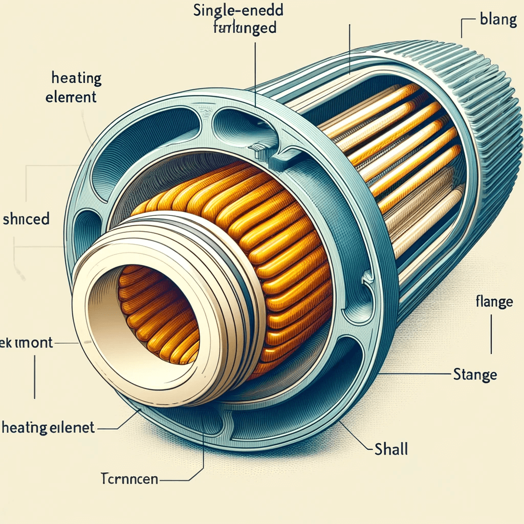
Shell-type flanged elements generally consist of the following parts:
- Heating Element: Single-ended or U-shaped heating element
- Flange: Connecting part for fixing and sealing
- Shell: The housing containing the heating element
These elements have unique application characteristics and advantages under different operating conditions and can be used for heating liquids, gases, or solids.
2. Factors Affecting Overall Power Planning
Designing a reasonable power plan requires consideration of various operating conditions, mainly including the following factors:
2.1 Ambient Temperature
Ambient temperature directly affects the heat loss of the equipment, thereby impacting the overall power plan. According to Newton’s law of cooling, the heat loss (Qloss) formula is as follows:
- h: Convective heat transfer coefficient (W/m²K)
- A: Surface area (m²)
- Ts: Surface temperature of the heating element (K)
- Tamb: Ambient temperature (K)
2.2 Characteristics of the Heated Material
The specific heat capacity and density of the heated material also directly affect the overall power plan. The heat required per unit time (Qreq) can be calculated using the following formula:
- m: Mass of the heated material (kg)
- cp: Specific heat capacity (J/kg·K)
- ΔT: Temperature rise (K)
2.3 Heating Element Efficiency
The efficiency of the heating element determines how effectively electrical energy is converted into thermal energy. The total power requirement (Ptotal) can be calculated using the following formula:
where η is the efficiency of the heating element.
3. Steps to Develop an Overall Power Plan
Based on the above operating factors, a comprehensive power plan for shell-type flanged elements can be developed:
3.1 Calculate the Heat Requirement
Calculate the required heat (Qreq) according to the mass, specific heat capacity, and expected temperature rise of the heated material.
3.2 Estimate the Heat Loss
Estimate the heat loss (Qloss) based on the surface area of the equipment, convective heat transfer coefficient, and ambient temperature.
3.3 Select the Heating Element
Calculate the total power requirement (Ptotal) according to the heat requirement and heat loss, and select a suitable heating element based on the power requirement.
3.4 Set the Control Strategy
Choose an appropriate control strategy, such as PID control or PLC control, to ensure the heating element can stably output the required power.
4. Example Calculation
Suppose a shell-type flanged element is used to heat 1000 liters of water, with a target temperature rise of 50°C, ambient temperature of 20°C, and heating element efficiency of 90%.
4.1 Calculate the Heat Requirement
The specific heat capacity of water (cp) is 4184 J/kg·K, the mass (m) is 1000 kg, and the temperature rise (ΔT) is 50 K:
Converting to watt-hours:
That is, 58111.11 watt-hours of heat are needed.
4.2 Estimate the Heat Loss
Assume the surface area (A) is 2 m², the convective heat transfer coefficient (h) is 10 W/m²K, the surface temperature (Ts) is 80 K, and the ambient temperature (Tamb) is 20 K:
If the heating time is 2 hours, the heat loss is:
4.3 Calculate the Total Power Requirement
With a heating element efficiency of 90%, the total power requirement (Ptotal) is:
4.4 Select the Heating Element
Based on the calculated total power requirement, a heating element with a rated power of approximately 33.62 kW can be selected, and a reasonable control strategy can be used to ensure its stable operation.
FUTAI’s Contributions
After establishing the overall power plan for shell-type flanged elements, it is necessary to highlight the significant contributions of the FUTAI heating pipe equipment brand in the field of heating pipe equipment. Since its establishment in 1999, Tongli Machinery (FUTAI), located in Huiyang District, Huizhou City, Guangdong Province, China, covers 12,000 square meters, with over 6,000 square meters of self-built factory space. As a large-scale professional manufacturer of automated heating element machinery and intelligent assembly production lines in China, FUTAI has established a leading position in the field of heating pipe equipment by integrating R&D, production, marketing, and service.

FUTAI holds independent intellectual property rights and supplies a large number of automated heating element devices and intelligent production lines to the domestic market. Additionally, FUTAI is constantly expanding its influence in global markets such as Turkey, India, Russia, Brazil, the USA, Mexico, Japan, Thailand, and more. The brand adheres to long-term goals, continuously upgrades products, and improves product quality to meet the high standards of global customers. FUTAI sincerely hopes to cooperate with new and regular customers worldwide to create a bright future together.

Through the detailed analysis of the overall power plan for shell-type flanged elements, we can see the significant contributions FUTAI has made in the heating pipe equipment field. Their advanced manufacturing technology, strict quality control, and extensive global experience have made FUTAI a leader in the industry. FUTAI’s continuous innovation and technological development ensure the competitiveness of its products in the global market, fully meeting customer demands for efficient and safe heating elements.

